CV Input Signal Types #6 — Envelope CV

| Property | Value |
|---|---|
| Category | Unipolar / Modulation |
| Voltage Range | 0..+8V (Doepfer standard), some modules 0..+5V |
| Polarity | Unipolar |
| Bandwidth | DC..~2kHz (fast attack phases <0.5ms) |
Description
Envelope CV is the output of an envelope generator (ADSR, AD, AR, etc.) used as a control voltage for other modules. It represents the temporal shape of a note — from the attack through the hold time to the decay.
Use Cases
- VCA control (volume contour of a note)
- Dynamically control filter cutoff (brighter on attack, darker on decay)
- Open/close a low-pass gate (LPG)
- Pitch modulation (pitch envelope for percussive sounds)
- Control wavefolder amount
Eurorack Examples (Mutable Instruments)
- Plaits: LEVEL input acts as internal VCA opener or LPG trigger, depending on mode
- Rings: Envelope at BRIGHTNESS modulates tonal character
Hardware Implementation
Input Stage: OpAmp → Mux → ADC
Same inverting summing amplifier topology as V/Octave, but with lower precision requirements (1% resistors, MCP6004 suitable).
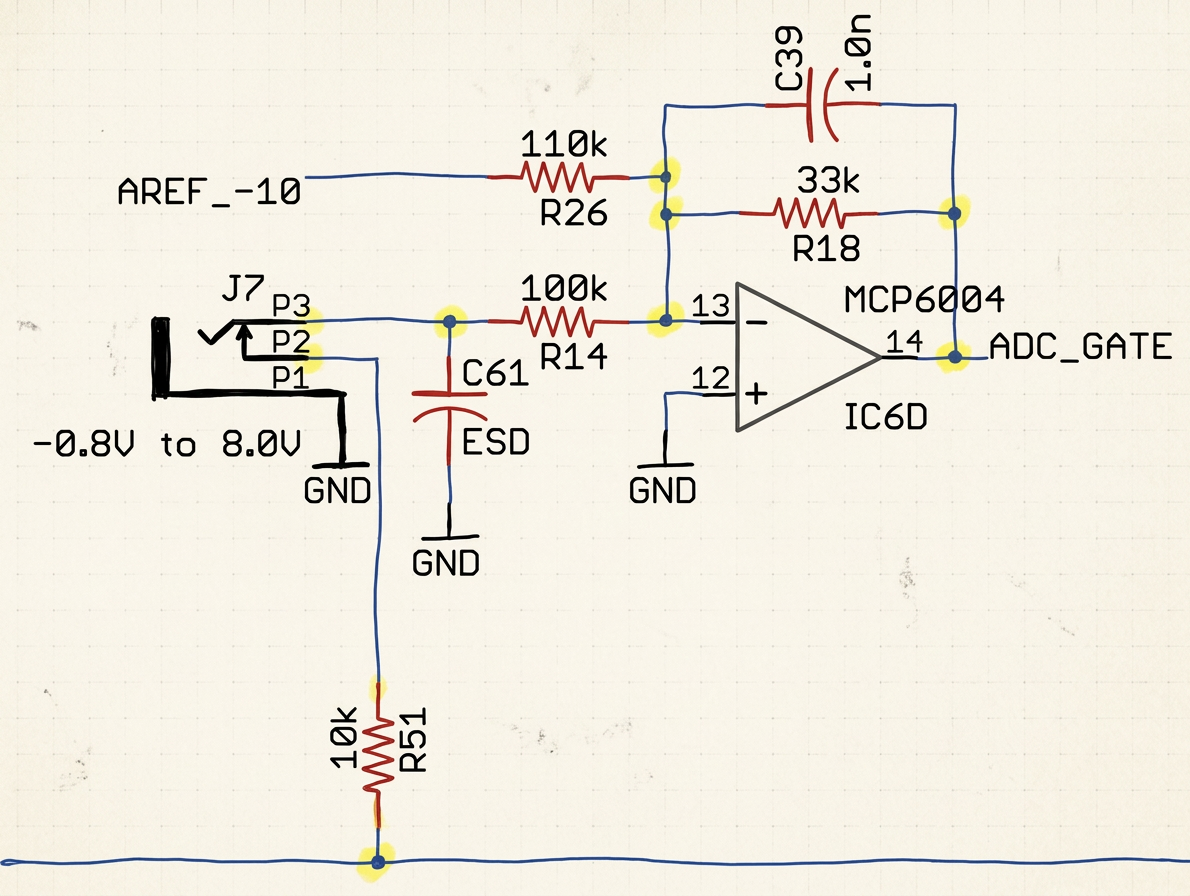
About the ADC_GATE label: The net is named ADC_GATE in the Plaits schematic, but LEVEL on the front panel. ADC_GATE refers to the logical function (gate/trigger detection), while LEVEL emphasizes the envelope function. Because Plaits reads this input via the ADC (SDADC, 16-bit) — not via a GPIO as in Stages — the firmware receives the full analog voltage value. This allows the same input to serve both as a continuous envelope CV (VCA control) and as a gate/trigger (threshold detection in software, LPG mode).
Clipping Problem with Signals >5V
The standard resistor values (R_in=100k, R_ref=200k, R_fb=33k) are designed for -5V..+5V. Eurorack envelopes can reach up to +8V (Doepfer standard):
- V_in = +8V → V_out = -(8 × 0.33 - 1.65) = -0.99V → clips at 0V!
- Everything above +5V is read as +5V.
Solutions:
- Accept it: If only 0..+5V envelopes are expected, the standard stage suffices.
- Increase R_in: e.g., R_in=150k for range 0..+8V → V_out at +8V = -(8 × 0.22 - 1.65) = +0.09V (tight but not clipped). Disadvantage: resolution decreases.
- Separate input stage for 0..+10V with adjusted resistor values.
Firmware Requirements
- Sample rate: At least 4–10kHz for envelope inputs, to correctly capture steep attack phases (<0.5ms). Too low a rate = envelope peak is missed, sound loses "punch".
- No aggressive low-pass filtering — attack transients must be preserved