Pulser #3 — Tempo
A fixed speed is useless in music. So there must be a way to change the speed. I follow the Beats Per Minute (BPM) convention. I've set a range of 30 BPM to 300 BPM.
At a given resolution of 24 PPQ, you can calculate what frequency the clock ticks must have. This then determines the value of the pause counter in the PIO state machine.
Button State Machine
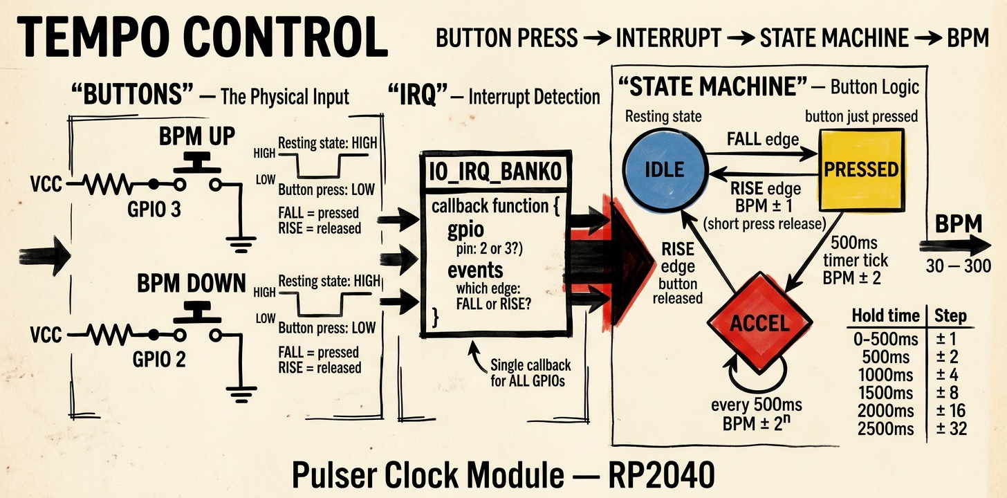
For adjustment, there are two buttons that increment or decrement by varying amounts depending on how long they are pressed. This means if I press briefly once, it changes the BPM by ±1. If I press longer, the change gets larger. The longer I press, the bigger the jumps, the faster the value changes.
This is implemented via a state machine with three states: IDLE, PRESSED, ACCELERATING.
Press and Release Detection
To avoid burdening the CPU, the detection of whether and which button is pressed or released is handled in an interrupt.
On the RP2040, all GPIO pins share one interrupt. You can define for each pin which edges trigger the interrupt and then receive in the interrupt handler which pin and which edge the call pertains to. The handler then needs logic to evaluate this.
The buttons are connected to VCC via external pull-up resistors. In the idle state, the pin is HIGH. When pressed, the button pulls the pin to GND.
The pulser thus evaluates the rising and falling edges of GPIO 2 and GPIO 3. These events control the state transitions of the state machine. A timer measures how long the state machine remains in the ACCELERATING state because a pin is held at GND.