Pulser #4 — Output
Display
Since I had an old 7-segment display lying around, I use it to show the current BPM value. The display has an HT16K33 controller and is driven via I2C. The display is right-aligned.
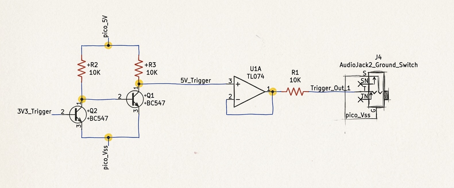
Output
The 24 PPQ clock ticks, which are present as 3.3V trigger signals on GPIO-16, are amplified to 5V and output directly to a CV mono jack via a buffer.
There are 4 output jacks to allow the clock to be sent to multiple modules simultaneously.