
Trigger
| Property | Value |
|---|---|
| Category | Logical / Time-Based |
| Voltage Range | 0..+5V (tolerant up to +12V) |
| Polarity | Unipolar |
| Bandwidth | <1kHz (pulses 1–10ms), edge case: audio-rate |
| Threshold | ~0.7V–2.0V (module-dependent) |
Description
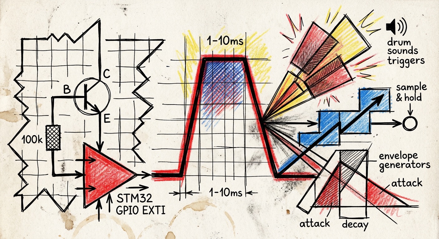
A trigger is a short voltage pulse (typically 1–10ms duration) that initiates a one-time event. Unlike a gate, only the rising edge matters — the pulse duration has no musical significance.
Audio-rate edge case: Some patches use audio oscillators as trigger sources (e.g., for audio-rate triggering of envelopes for AM synthesis or granular grains). The firmware must handle this without overloading the CPU through interrupt storms.
Use Cases
- Start an envelope (ADSR/AD)
- Trigger a drum sound or sample
- Strike a resonator (e.g., Karplus-Strong "strum")
- Advance a sequencer step
- Sample & Hold capture
- Ping (exciting Vactrols or low-pass gates with very short impulses)
Eurorack Examples (Mutable Instruments)
- Plaits: TRIG input starts the internal decay envelope and strikes the oscillator
- Rings: STRUM input excites the resonator (Karplus-Strong)
- Stages: Trigger advances between segments
Hardware Implementation
Recommended: GPIO (not ADC)
Triggers must not be read via a multiplexed ADC. The mux cycle (typically ~1ms) introduces up to 1ms of random jitter — audible as "flamming" in tight drum sequences.
Method 1: NPN transistor inverter (preferred)
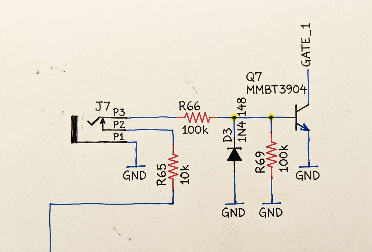
- Jack tip → 100k series resistor → NPN base (BC847)
- 100k base bleeder resistor to GND (forms voltage divider, raises effective threshold to ~1.2–1.4V, prevents false triggers from noise)
- Emitter → GND
- Collector → 10k pull-up to 3.3V → STM32 GPIO (EXTI)
- Advantage: survives ±12V, defined threshold
- Disadvantage: signal is inverted (invert in software with
!)
Method 2: Passive clamping (BAT54S)
- Jack tip → 47k series resistor → GPIO
- BAT54S dual Schottky: clamping to GND and 3.3V
- 100k pull-down, 1nF EMI capacitor
Firmware Requirements
- EXTI (External Interrupt) configured for rising edge
- Lockout timer (1–2ms) after detected trigger to prevent bounce/double triggering
- Audio-rate protection: If interrupt storms are a risk (audio signal at trigger input), consider polling in block-rate interrupt instead
- Optional: hardware timer input capture for precise timing (μs resolution)
- Optional: 74HC14 Schmitt trigger before GPIO for clean edges